Probing with a non-conductive object such as a chopstick while the amp is powered on is a good way to find bad connections or problems with the way the wiring is laid out.
An incorrect voltage (far away with reference voltages) may give a clue to the source of the problem.
1.A low voltage often indicates that something is drawing more current than the power supply can handle and dragging down the voltage.The too low voltage commonly caused by :Short, leaky capacitor, incorrect resistor value, or mis-wiring.
2. The high voltage often indicates that load is few or missing. Too high voltage commonly caused by Missing load (open resistor, uninstalled tube, wrong value resistor).
3.Zero volts where there should be B+: Possible short to ground or bad solder joint
4. Wrong cathode voltages: Bad tube, wrong resistor, or reversed wiring.
1.The interior of a tube guitar amp contains fatal high voltage. If you do not have sufficient skill and experience with high-voltage circuits, do not attempt to test it.
2. Never operate the amp without a load.It will damage the output transformer. You can use an 8 ohm 30 watt power resistor as a dummy load in place of a speaker.
Below are the status readings of the amp while the voltage map of the JCM25 main board is being measured. Please adjust your amp according to these values. Due to slight variations in electronic components, a 10% fluctuation between the voltage values measured from your amp and the data in this voltage map is normal..
Voltage: DC
Standby ON
Contol: Gain and Master minimum
Biase voltage: -30V
Power tube: Pentode
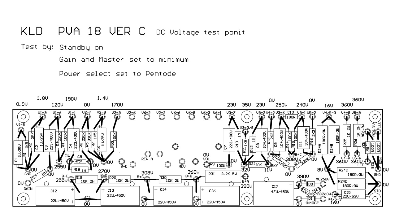
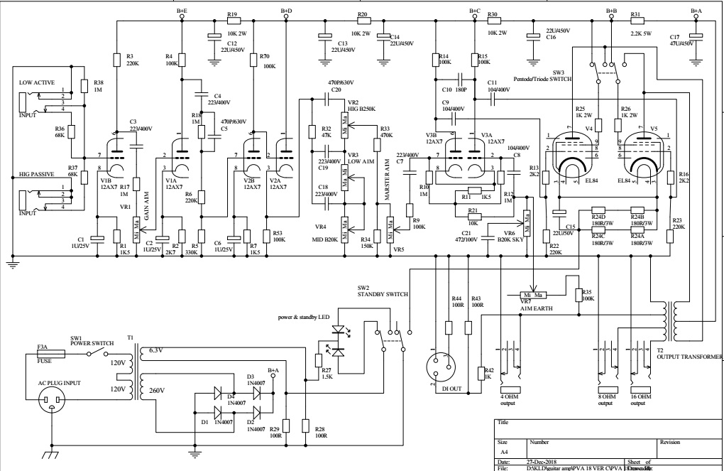
Filter circuit of power
Let’s take a look at the circuit board from the side where the components are installed. From bottom to top, the power supply filter circuit is located at the bottom of the board. The farthest right is the rectifier bridge, made up of four diodes (D1-D4), which provides full-wave rectification for the 260 VAC from the power transformer. Moving from right to left, through various capacitors that filter the power, the different plate voltages for the tubes in the amp stages are as follows: B+A: 390VDC, B+B: 360VDC, B+C: 308VDC, B+D: 270VDC (V2), and B+E: 255VDC (V2).
If you don’t hear any sound after turning on the amp, first make sure the voltages are normal. Then, check the pins connected to those voltages in the tube sockets. The plates of the 12AX7 are on Pin 1 and Pin 6, while the plate of the EL84 is on Pin 3
Position code
The uppest line of the main board. Each hole has the position code of one letter and two digits . The first letter "V" represent "Valve (Tube)". First digit means code of the tube, second digit means code of the pin of the tube. For example: V2-3 represent this hole will be connected with the Pin3 of second tube.
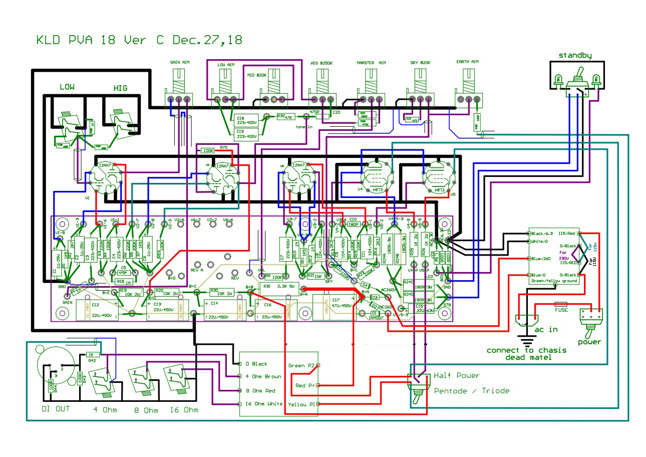
Because this main board is universal board of our amps, so the position codes printed on board are not totally consistent with the real layout drawing of the each amp. Please connect wires according to layout drawing of each amp kits.
First preamp
PVA 18 has three preamp stages, V1B, V1A, V2B. The voltages of first 12ax7 tube are below: The plate voltage of V1B is 120VDC (V1-6 of board), the plate voltage of V1A is 190VDC(V1-1 of board). The cathode voltage of V1B is 0.9VDC (V1-8) and V1A is 1.8VDC (V1-3), the second amplify stage(V1A) is clod cathode bias.Make sure your tubes working around these quiescent point(q-point). If their working point were far away with these q-points, the periphery circuits of tube must have problems.
The second tube V2B is the third stage preamp, V2A is high voltage cathode follower which mainly adjust the impendance of amp. Pin7 is grid of V2B, it connected with V2-7 of the board, voltage is 0VDC. Pin8 is the cathode of V2B, it connects with V2-8 of the board, the voltage is 1.4VDC. Pin3 is the cathode of V2A, It connected with V2-3 of the board, the voltage is 170VDC.
Long Tail Pair phase inverter
The third tube is long tail phase(LPT) inverter of PVA18 amp.The grids ( Pin2, 7 ) of V3 connect with V3-2 and V3-7 of the board, the voltages are 23 VDC all. The plates ( Pin1,6) of V3 connect with V3-1 and V3-6 of the board, the voltage of V3-1 is 240 VDC and V3-6 is 250 VDC. The cathodes of V3 are Pin3 and 8 of the tube, they connect with V3-3/8 of the board , the voltages are 35VDC all.
Class AB power amp
EL84 has nine pins. Pin4 and 5 are pins of filament. Pin7 is plate(Anode). The pin 9 is grid 2(Screen grid), Pin2 is grid 1( Control grid). Pin 3 is cathode or grid 3(Suppress grid), and three NC pins ,Pin 1,Pin6, Pin8. The type of power amp stage of PVA18 is Class AB: V4 and V5. The pins of these two tubes connect with the main board include: Two Pin 5s(Filament) connect with board 6.3VAC.Two Pin9s(Grid 2) connect with V4-9,V5-9 of the board individual, the voltages are 360VDC all.The Pin 2 of two tubes (Grid1) connect with V5-2 and V4-2 of the board, the voltages of them are 0VDC all. The Pin3 of V4 and V5(Cathode) connect with V4/5-3 of the board, the voltage is 16VDC.
The static operating points is important parameters describing status of amp, it is useful tool to troubleshoot. Abnormal operating points always means not only connection in mistake, but also possibility of resonance in the circuit.