Probing with a non-conductive object such as a chopstick while the amp is powered on is a good way to find bad connections or problems with the way the wiring is laid out.
An incorrect voltage (far away with reference voltages) may give a clue to the source of the problem.
1.A low voltage often indicates that something is drawing more current than the power supply can handle and dragging down the voltage.The too low voltage commonly caused by :Short, leaky capacitor, incorrect resistor value, or mis-wiring.
2. The high voltage often indicates that load is few or missing. Too high voltage commonly caused by Missing load (open resistor, uninstalled tube, wrong value resistor).
3.Zero volts where there should be B+: Possible short to ground or bad solder joint
4. Wrong cathode voltages: Bad tube, wrong resistor, or reversed wiring.
1.The interior of a tube guitar amp contains fatal high voltage. If you do not have sufficient skill and experience with high-voltage circuits, do not attempt to test it.
2. Never operate the amp without a load.It will damage the output transformer. You can use an 8 ohm 30 watt power resistor as a dummy load in place of a speaker.
The DC voltage map of Bassman25 main board is measured at these status. Please adjust your amp to these status.Because there are a little differents between the electronic components,the 10% fluctuation between voltage values measured from your amp and datas in this voltage map is normal.
Voltage: DC
Standby ON
Contol: Gain and Master minimum
Biase voltage: -30V
Power tube: Pentode
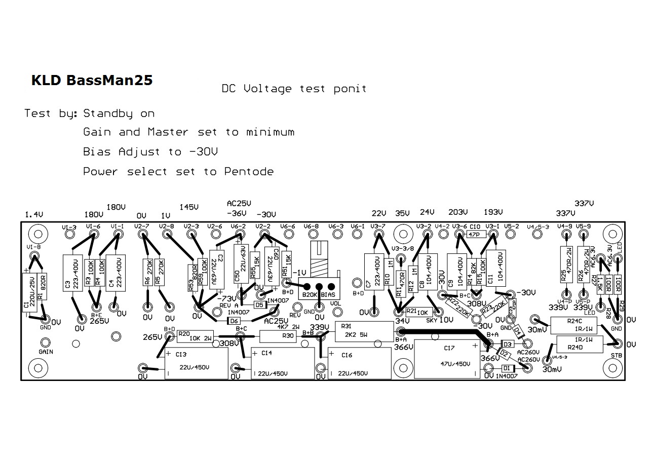
DC voltage map of main board
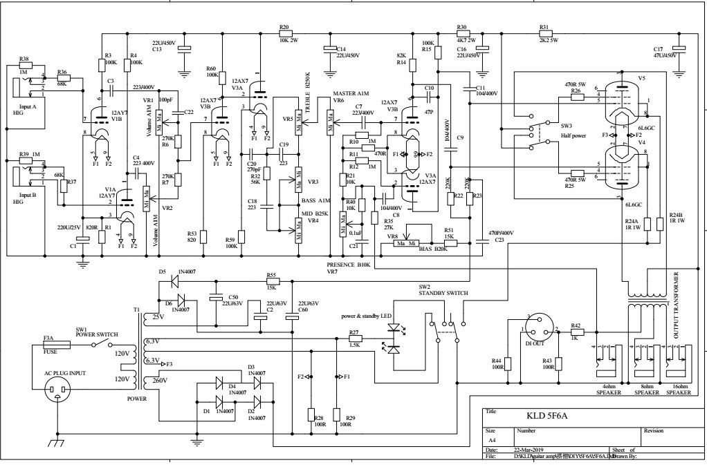
Filter circuit of power
Let us see the circuit board from the side which installed components. Down to up ,the power supply filter circuit is on the bottom of the board. The rightest is the rectifier bridge consisted by four diodes D1-D4, which provides full-wave rectify for 260 VAC from power transformer. From right to left, through different electrolytic capacitors filting , the different plate voltages of the tube in amp stages are: B+A: 366VDC, B+B: 339VDC, B+C: 308VDC, B+D:265VDC (V2).
If you could not hear any sound after turning on amp, please make sure these voltage normal first, then check the pins connected with them in tube sockets.The plates of 12ax7 are Pin1, 6, the plate of 6L6 is Pin 3.
Position code
The topmost row of the main board contains holes, each labeled with a position code consisting of one letter and two digits. The first letter, 'V,' represents 'Valve (Tube).' The first digit indicates the tube number, and the second digit represents the tube pin number. For example, 'V2-3' means this hole should be connected to Pin 3 of the second tube.
Since this main board is a universal board for our amps, the position codes printed on the board may not exactly match the layout drawing for each specific amp. Please refer to the layout drawing for your particular amp kit when connecting the wires.
First preamp
Bassman 25 has dual independent channels, which are individual amplified by the two amp of the first 12ax7. The plate voltages of two amp are 180VDC all, and cathode voltages are 1.4VDC all.The cathods Pin8 and 3 connect with V1-8 of the main board,the first amp of Bassman25 is warm bias. The plate Pin6 of V1B connects with V1-6 of the board, the plate Pin1 of V1A connect with V1-1.
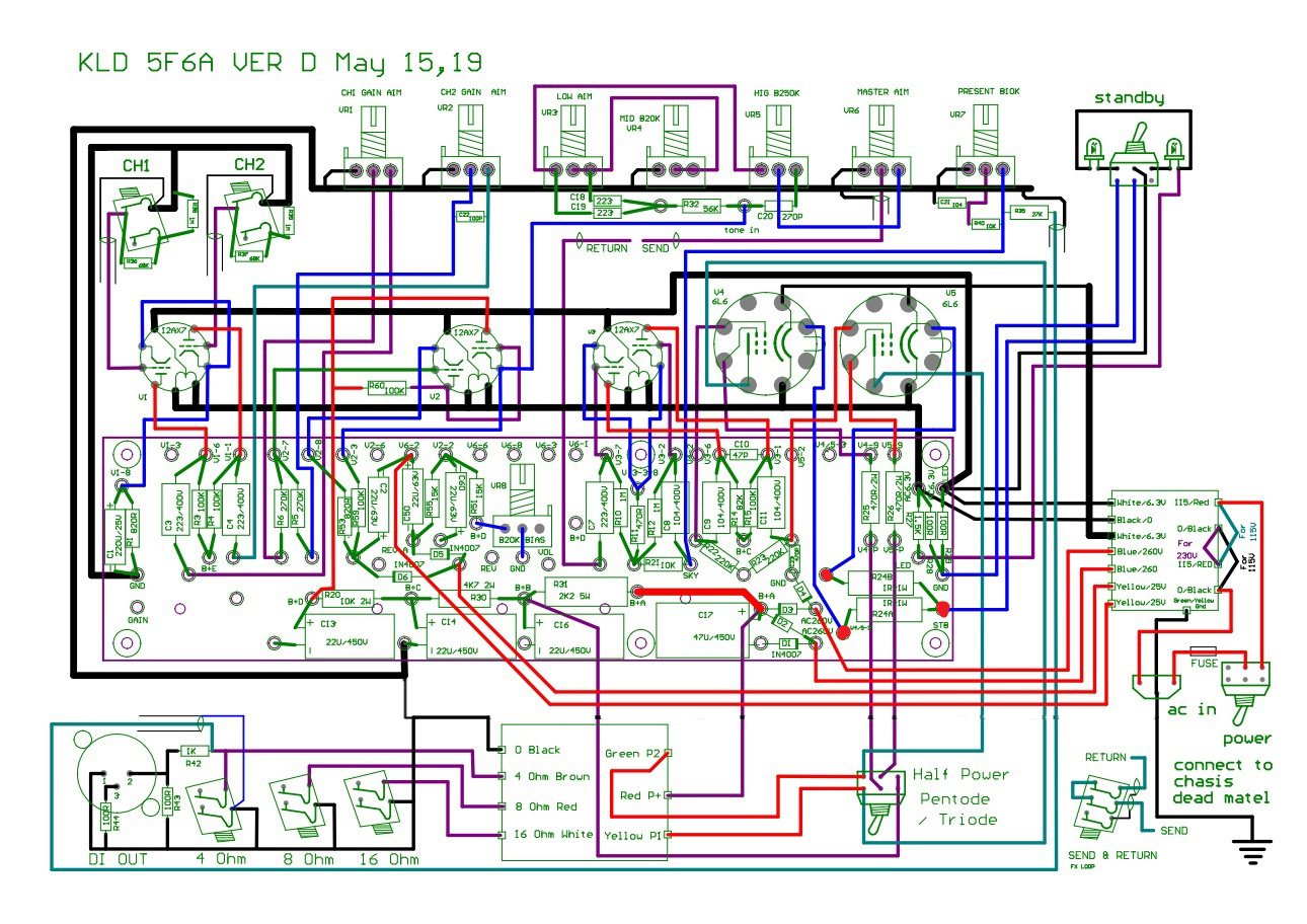
V2B is the second stage preamp, V2A is high voltage cathode follower which mainly adjust the impendance of amp. Pin7 is the grid of V2B, connects with V2-7 of the board, the voltage is 0VDC. Pin8 is the cathode of V2B, connects with V2-8 of the board, the voltage is 1VDC. The cathode of V2A (Pin 3) connects with V2-3 of board, the voltage is 145VDC.
The third tube is Long Tail Pair phase inverter of Bassman25 amp.The grids (Pin2,7) of V3 connect with V3-2 and V3-7 of the board. The voltages of these two holes are 22VDC all. The plates(Pin1,6) of V3 connect with V3-1 and V3-6 of the board, the voltage of V3-1 is 193VDC and V3-6 is 203VDC. The cathodes of V3, Pin3 and 8, connect with one hole of the board V3-3/8, the voltage is 35VDC.
The power tube of Bassman25 use octal tube such as 6L6, EL34 etc . The values of DC voltage map are measured utilizing 6L6 tube. Pin2 and 7 of 6L6 are pins of filament. Pin3 is plate. Pin 4 is grid2(Screen), Pin5 is grid1. Pin8 is cathode and beam plate.
Bassman25 is Class AB amp: two paired 6L6 tubes V4 and V5. Because V4 and V5 are paired, so all voltage values of these two tubes are same. The pins of these two 6L6 connect with the main board include: Pin2s(Filament)of of V4 and V5, connect with board 6.3VAC; Pin4s(Grid 2) of V4 and V5, connect with V4-9,V5-9 of the board, the voltage is 335VDC all; Pin5s(Grid 1), connect with V5-2 and V4-2 of the board, the voltage is -30VDC all; Pin8s (Cathode) connect with V4/5-3 and R24C of the board, the voltage is 30 mVDC all.
The static operating points is important parameters describing status of amp, it is useful tool to troubleshoot. Abnormal operating points always means not only connection in mistake, but also possibility of resonance in the circuit.