Capacitors used in tube guitar amp |
| A capacitor is simply two electrical conductors separated by an insulating layer called a dielectric. The conductors are usually thin layers of aluminum foil, while the dielectric can be made up of many materials including paper, mylar, polypropylene, ceramic, mica, and even air. Electrolytic capacitors have a dielectric of aluminum oxide which is formed through the application of voltage after the capacitor is assembled. Characteristics of different capacitors are determined by not only the material used for the conductors and dielectric, but also by the thickness and physical spacing of the components. |
 |
|
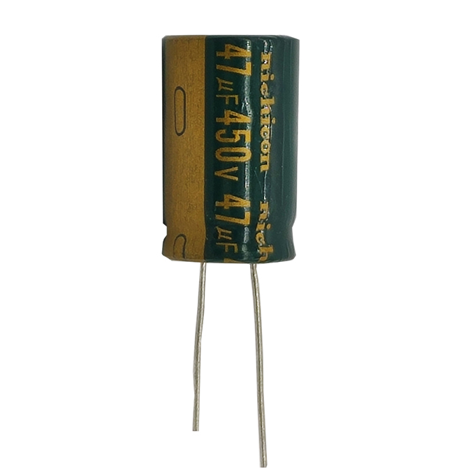
Decreasing the capacitance of a filter capacitor decreases its storage space, making less charge available to power the amp. During peak demands, like a percussive bass note or a sudden chord, the voltage supply will sag. When the voltage supply sags, the gain of the amplifier goes down. Then, when the demand subsides, the gain goesback up. This gain compression can be musically desirable, improving the "feel" of the amplifier as it self-adjusts to the player's attack.
|
 |
2. Cathode Bypass Capacitor |
 |
Cathode-bypass capacitors are used to counteract some of the frequency and gain-dampening tendencies induced by the cathode-bias resistors they are coupled with. Both preamp and output tubes need to be biased,and while a resistor is used for the technique in the output stages of only a specific class of amplifier.
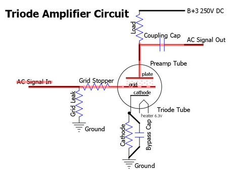
Let us first review works of tubes amplifier bias: There are three main parts in vacuum tube: grid(Base), anode plate(Collector), cathode(Emitter). The Cathode is the source of electrons; The plate is charged with high voltage DC to pull electrons from the cathode; The grid controls the flow of electrons from the cathode to the anode plate according to input signal fluctuating. When a negative voltage is applied to the grid, the positive pull of the plate is partially negated, decreasing the flow of electrons through the tube. Furthermore, a fluctuating negative voltage on the control grid causes a fluctuating electron current through the tube. In this way, a small signal voltage is amplified into a heftier, more powerful signal current. (a)Amplifier Bias When a vacuum tube is amplifying signals, the level of negativity on its control grid is important. The starting value (before any signal is applied) is called the "bias" value. The negative bias must be more than the largest positive swing of the signal. Otherwise, the grid would turn positive and siphon off electrons as they pass through. On the other hand, the bias mustn't be overly negative. The bias is just right when the vacuum tube amplifies linearly (i.e. with its output current directly proportional to its input signal. (b)Cathode Bias A positive bias on a valve's cathode is equivalent to a negative bias on its control grid - the control grid remains more negative than the cathode and it continues to receive the signal voltage. Cathode bias is created by a resistor between the cathode and ground.the value of that resistor is determined according to how “hot” this stage amp is, relative to operating voltages and in terms of gain factors and so forth). Electrons flow up through the resistor from ground, putting the cathode at a higher-than-ground (positive) potential. This resistor also induces a form of negative feedback in that tube, which tamps down the gain and flattens the frequency response. (c)Cathode Bypass Capacitor Cathode bypass capacitors are not absolutely necessary in a circuit. However, their presence or absence in an amplifier affects three things: 1. Gain 2. Frequency response 3. Hum Cathode bypass caps are wired in parallel with cathode bias resistors in order to conduct AC signals around the bias resistor. Without a bypass cap, alternating current flows through the bias resistor, alternating the tube's bias and linearity, distorting the signal's dynamics. Signal waveforms also distort. Wave crests add more bias, lowering the tube's gain, flattening the crests, while wave troughs create less bias, raising the tube's gain, deepening the troughs. Cathode bypass caps are usually electrolytic types, unless smaller than 1uF. Decreasing & increasing Bypass Capacitance The cut off Freq of capacitor is below: f(cutoff)=1/(2*3.14*R*C) The smaller capacitance is, the high cutoff Freq is, the higher capacitive reactance of capacitor is, the bigger impedance to low Freq is. Decreasing a cathode bypass capacitance forces low frequencies through the bias resistor, increasing the tube bias and decreasing the gain at those frequencies. As a result, a smaller bypass cap yields less bass and more apparent treble while a larger bypass cap yields more bass and less signal alteration The RM below the wiper comes after the low pass filter, which let some mid and high freq signals pass through the filter. Only turning the RM to zero, the RS + CM low pass filter could cut off all frequencies above cutoff, let bass freq signals pass to the RT. 3.Stage Coupling Capacitor Stage coupling capacitors are to pass AC signals from one amplifier stage to the next while blocking any DC current. A coupling capacitor that leaks direct current creates a DC voltage on the input of the next stage. This voltage could interfere with the bias of the stage or damage its parts. Decreasing & Increasing coupling capacitance Since a small capacitance blocks more low Freq signals than a large capacitance, decreasing the coupling capacitance reduces the amount of bass tone passed along to the next stage. On the other hand, increasing the coupling capacitance allows more bass tone to pass. |
 |
4.Tone control capacitor We only discuss the key characteristics of capacitors used in Tone Stack here.
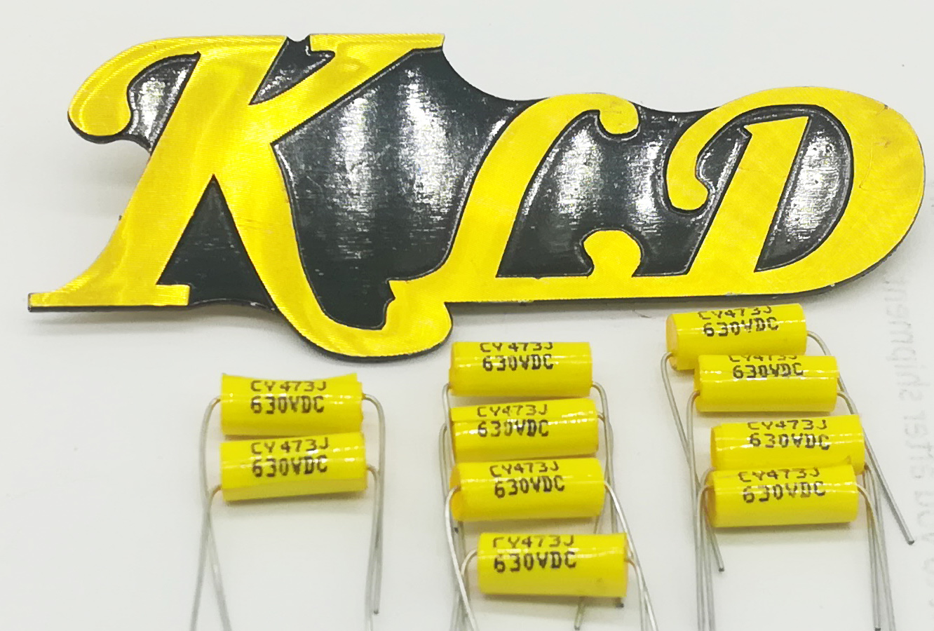
The capacitors used in stage coupling and tone stack are commonly film capacitor, including polyester, polystyrene, and polypropylene. The capacitor used in the Tone Stack of KLD amp is CBB20 Polypropylene.The CBB20 polypropylene capacitors uses self-healing polypropylene film dielectric with vacuum evaporated metal electrodes. Tinned axial wire leads are electrically welded to the metal contact layer at the ends of capacitor winding. The winding is wrapped in mylar tape and the ends are sealed with epoxy resin. |